I've been looking for a project to do in my spare time for a while now and the one I've always had on the back of my mind is a 3-axis gantry CNC router. A CNC gantry router would be a really nice tool to do things like cutting and drilling PCB's, machining small aluminum parts and for my wife to surface jeweler's wax with. At work I used EMC2 and some Probotix stepper controllers and stepper motors to retrofit one of our small lathes. It turned out great, was a pleasure to do and ignited an even greater hunger for CNC machinery in me.

A shot of "the thing" after I had taken the imaging mechanism off the X-Y gantry
What finally catalyzed my initiative to begin was a gadget I found at a surplus warehouse in Morgan Hill, CA that was both a huge bargain and about 80% of the hardware I needed to build the thing! I'm a little bummed I didn't take a picture of it before I began stripping it down because it was a pretty interesting contraption that I think came out of
some kind of optical inspection equipment. But you can see a crappy picture of it post-partial-tear-down above.
It consisted of a 2-axis stepper/ball-screw gantry with a high quality computer vision system camera mounted to it facing downward. The camera was pointed through a slotted aperture with about 30 red SMD LED's all around it to illuminate the subject. The whole camera assembly could be swiveled 90 degrees with a rotary pneumatic actuator (so really a 2.5-axis gantry or something). A third stepper/ball-screw axis was separately attached to the base and had a pneumatically actuated gripper to grab whatever was to be inspected I suppose. I imagine the thing came out of an electronics quality control machine in a fab somewhere here in Silicon Valley, but that's just speculation. So here's what I got for my $200 bucks:
- 3 good quality Pacific Scientific unipolar stepper motors
- 3 working Centent CN0162 microstepping stepper controllers - kind of an old design but those babies were like $500/each new 10-15 years ago.
- 3 ball-screw linear axis assemblies with high-quality linear bearings. Ball screws, for those that don't know, are wonderful for CNC because they have almost no backlash. Essentially all high quality CNC machines use ball screws.
- A rigid custom-machined aluminum gantry attached to a ~24in x 20in 1/2" aluminum base

X-axis ball screw

Centent CN0162 Microstepping controller (1 of 3)
The thing that really blows my mind about this thing is how much money was spent making it

initially. Ball screws aren't cheap and all of the sensors and other components are extremely high quality. The whole thing is made of custom milled aluminum parts bolted together. You can see at least 8-10 of these parts on the separate 3rd axis to the right. I did a rough tally of the 3rd party components in the device and I got a number in the $4000-$5000 range. With all the custom machining on top of that, this thing cost somebody $10k+ to build.
Anyway, I mentioned earlier that I had used EMC2 at work retrofit a lathe. The EMC2 LiveCD makes installing it on an old computer brain-dead and the only downside I can see is that you need hardware with a parallel port. In looking around the web a bit I noticed that the hard-core machine retrofitters all use EMC2 for control while the hobby/tinkerer/Arduino crowd are much more attracted to RepRap software and controls. I imagine this is due to the respective origins of the two projects but it's a bit unfortunate because I see some replication of effort between the two projects. Yes, RepRap is a FDM system and EMC2 is a general purpose machine controller, but I've seen at least one project (RepRap Cartesian Bot) doing 3-axis router control with RepRap. I actually really like the new RepRap control architecture but I chose to go with EMC2 because:
- I'm familiar with it
- I already have stepper controllers that will be easy to integrate with a parallel port interface
- It will run a full-featured G-Code program (the RepRap's G-Code interpreter is fairly limited as far as I can see)
- The AXIS interface to EMC2 is extremely nice and customizable using Python
Progress To-Date
The first thing I set out to do was strip the machine of everything I didn't need for the router and get it set up in my garage with the computer that would be controlling it (my wife's ancient HP from college).

The setup
EMC2 is very well setup for stepper motor control has a nice GUI tool called stepconf wizard for setting up the parallel port I/O and relevant timing for the stepper controllers.
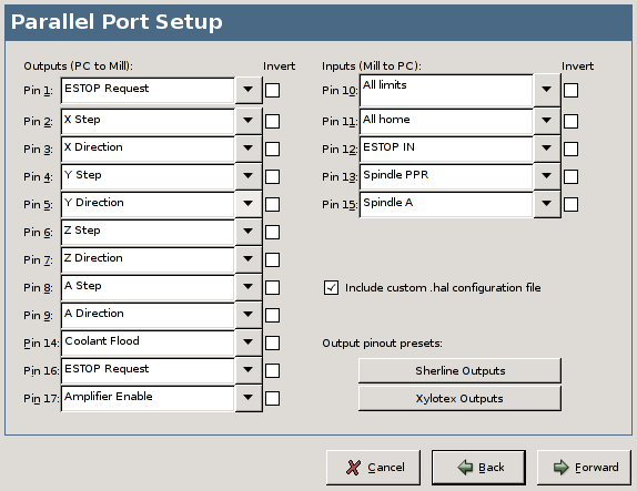
Stepconf wizard. Credit AXIS website.
The Centent controllers have optoisolators on the step and direction inputs and while I suspect the parallel port would have been able to drive them, I went ahead and used a ULN2803 darlington array to drive the optoisolator LED's. The anodes of the optoisolator LEDs are tied to the 5V supply and the step and direction inputs are connected to the cathodes making them ideally suited to be driven with an NPN transistor array such as this.

Schematic of parallel port output buffer
After a bit of tinkering and one fried 7805 voltage regulator, I got the all three axis of working with EMC2.

The prototype wiring. The ULN2803 and 7805 voltage regulator are both soldered to the prototyping PCB on the right. It will be cleaned up later...
Just for the heck of it I taped a permanent marker to the gantry and used it to draw the EMC2 AXIS logo. It came out surprisingly well considering the marker was not held very well and the cardboard was flexing in the middle.

Worlds worst pen-plotter
Check out the video...
Future...
The next step is to make a rigid mount for the third (Z) axis on the gantry assembly. The third axis is pretty heavy as it exists now and I'm a little concerned about whether the XY axis will be able to control that much momentum. If worse comes to worst, I can machine off a lot of the material on the Z axis or even shorten it a bit to make it lighter.

The z-axis is a heavy beast
I spent a long time thinking about what to use for the spindle. On e-bay you can find some high power water-cooled router spindles but they're a bit pricey and, because they are 3 phase, require a variable frequency 3 phase drive. A water cooling system is not the end of the world, but it adds complexity. Dremel tools are often used, but they're probably underpowered and possibly not up to machining aluminum. I was at Harbor Freight the other day and saw this "Electric Cutout Tool" for $25. They also have a small handheld router for $22. Now I'm not saying that these are any more up to serious cutting than a dremel tool, but the cutout tool has a 1/2 hp motor in it and for $25, how can you go wrong?

The $25 harbor fright, I mean freight, special. What could go wrong??
Once I finish mounting the 3rd axis to the XY gantry, I will work on mounting the cutout saw. Because the saw uses a universal motor, doing speed control with a microcontroller should be fairly straightforward. I'm planning to use an AVR to do feedback speed control using speed set points from EMC2. I will probably used rectified PWM control rather than phase delay AC control in order to get better control properties and higher torque. I may even make the control board Arduino compatible... but we'll see. More on this little sub-project later.